First the user must perform a simulation of the circuit, then select a sub-circuit to enable this option.
The circuit needs at least one AC-source with Tstart<0 in order to produce steady-state output. There is no need to add measurement switches.
ATPDraw extracts steady-state phasor (time zero) from the LIS-file and arrange this according to the horizontal position .
All selected LCC components (not template) will have the voltage, current and power phasors corresponding to their node names extracted from the LIS-file. The extracted phasors will further be sorted according to the horizontal x-position of the LCC objects, and plotted as a function of the accumulated x-position. There is no restrictions on the number of phases or the number of LCC sections, but the horizontal position needs to be consistent and unique. The number of phases also needs to be the same for all sections. All objects can be selected and components different from LCC will simply be ignored (LCC templates also ignored).
In the Line Phasor window Fig. 1 that appears, all the LCC objects are sorted according to their x-position. All sections are listed in a string grid and the selected phasor is plotted below as a function of position. The first column shows the selected phase (7 in this case), node names in-out and the section length in km. The voltage, current and power phasors are further listed. The user can select (from the combo box at the bottom) to plot voltage, current or power phasors as function of position (in km) along the line starting from the left. The sections do not need to have the same length and the plot will adjust accordingly.
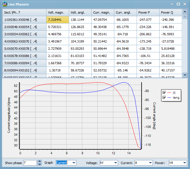
Figure 1. Line Phasor window. Example of 9-phase line containing 40 sections