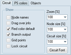
The View Options dialog can be used to control the visibility of the objects in the active circuit window. By default, all objects except node names, are visible. The following explains each option in normal checked (on) state:
Circuit:
Option |
Description |
Node names |
Force all node names to be written on screen. In general this looks bad and if the purpose is to identify a certain node name after an error message in the LIS-file a better alternative is to use ATP|Find node. |
Drag over info |
When on information about the component under the mouse cursor is shown in the Comment toolbar. Holding down Ctrl will also popup data values. |
Red color default |
Components and node dots are drawn with a red color until the component or node is opened (see Open Component, Open Probe and Open Node dialog boxes). |
Branch output |
When checked, small symbols will indicate the users selection of branch output. |
Grid points |
When checked small dots will appear in the circuit window indicating the possible node grid. |
Lock circuit |
When checked the circuit objects can not be selected and connections can not be drawn. This is a relevant setting for computer exercise situations. |
Zoom |
Default Zoom value |
Node |
Default Node size |
Circuit size |
Default % of 10000x10000 pixel circuit world. |
Circuit Font |
The default font used for various texts on screen. Only the main text object has its own font, while node names, labels, probe info uses the Circuit Font. |
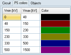
PS colors:
Setting of voltage ranges and associated colors used by the LINE3 power system toolbox component. Applies also to 3-phase Connections. Click on the color to change it. Specify range in kV.
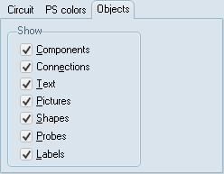
Object:
Option |
Description |
Components |
All standard and user specified components are displayed. |
Connections |
All connections (short circuits) are displayed. |
Texts |
All texts are displayed |
Pictures |
All pictures are displayed |
Shapes |
All shapes written on screen. |
Probes |
All probes (steady-state information) are displayed. |
Labels |
Component labels are written on screen. |


To accept the current view options and return from the View Options dialog, select the OK button. To set and view new options without returning, selected the Apply button. If you want the current settings to apply to all current and future circuit windows, select the Apply All button before you exit the dialog.