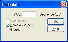
In the Open Node dialog you specify data for a single component node. There are four different kinds of nodes; each treated slightly different in this dialog box.
Parameters common to all nodes are:
Item |
Description |
Name |
A six or five (n-phase components) characters long node name. The parameter caption is read from the support file. If you try to type in a name on the reserved ATPDraw format (XX1234 for single phase or X1234 for three-phase nodes) you will be warned. Ignoring this warning can result in unintentional naming conflicts. |
On screen |
If checked, the node name is written on screen, regardless of the current setting of the Node names option in the View Options dialog box. |
UserNamed |
This checkbox shows whether this node name is specified by the user or ATPDraw. If the user wants to change a user specified node name he must do this where the UserNamed box is checked. If not, duplicate node name warnings will appear during the compilation. Node with UserNamed set are also drawn with a red node dot. |
The phase sequence appears after compile circuit is performed (ATP|Run ATP or ATP|Sub-process/Make node names). Transposition is only possible for 3-phase nodes. A four-phase node will have the phase sequence A..D. The user can connect a single phase connection to this node and specify which phase to connect to in the Connection dialog.
The following list explains the type specific node parameters.
Standard and user specified component node:
Short circuit If checked the multi-phase node is forced to be single phase.
Ground If checked, the node is grounded. Click on the ground symbol to rotate it.

The Open Node dialog box for standard and user specified components.
Model node:
Selection |
Description |
Output |
MODEL variable declared as OUTPUT. |
Input Current |
The node must be connected to a switch node. Will take the current through the first switch connected to this node. |
Input Voltage |
Will take the voltage to ground of the connected electrical node. |
Input Switch |
The node must be connected to a switch node. Will take the status of the first switch connected to this node. |
Input Machine |
For synchronous machines type 58/59, TACS nodes can be defined than such input should be connected to. For universal machines, a EMTP_OUT component where the internal machine variable is specified must be connected. Mechanical parameters taken from electrical network as Voltage (speed) or Current (torque). |
Input TACS |
TACS node must be connected. |
Input Im(SSU) |
Imaginary part of steady-state node voltage. Real part of the phasor is node voltage at T=0. |
Input Im(SSI) |
Imaginary part of steady-state switch current. Real part of the phasor is switch current at T=0. |
Input MODEL |
Connect the output from other model. Note that the model that produces this output must be USEd before the current model. This is done by assuring the correct sequence of models in the Sidebar|Project/Object tree. The older method is to specifying a lower group number for the model and then select the Sorting by group number option under ATP|Settings/Format. |
Input ATP |
Type in global ATP variable. MNT=simulation number... |
Input PL4 |
Loads signal from an pre-opened PL4-file. $OPEN, UNIT=63 must be used in an Additional component. |
TACS node:Type 0=Output.
1=Input signal positive sum up.
2=Input signal negative sum up.
3=Input signal disconnected.
(only necessary if node name is user specified)
TACS controlled machine node:
Type 0=No control.
1=D-axis armature current. Out.
2=Q-axis armature current. Out.
3=Zero-sequence armature current. Out.
4=Field winding current. Out.
5=D-axis damper current. Out.
6=Current in eddy-current winding. Out.
7=Q-axis damper current. Out.
8=Voltage applied to d-axis. Out.
9=Voltage applied to q-axis. Out.
10=Zero-sequence voltage. Out.
11=Voltage applied to field winding. Out.
12=Total mmf in the machines air-gap. Out.
13=Angle between q- and d-axis component of mmf. Out.
14=Electromagnetic torque of the machine. Out.
15=Not in use.
16=d-axis flux linkage. Out.
17=q-axis flux linkage. Out.
18=Angle mass. Out.
19=Angular velocity mass. Out.
20=Shaft torque mass. Out.
21=Field voltage. In.
22=Mechanical power. In.