This component called XFMR was added to version 4.2 of ATPDraw in June 2005. The XFMR component is an implementation and extension of the work performed by Prof. Bruce Mork at Michigan Tech and his co-workers Fransisco Gonzalez-Molina and Dmitry Ishchenko. This project called "Parameter Estimation and Advanced Transformer Models for EMTP Simulations" was sponsored by Bonneville Power Administration. A series of report documents this work and his here used as references MTU4, MTU6 and MTU7. The implementation in ATPDraw was also sponsored by BPA.
Consult also the XFMR dialog help screen.
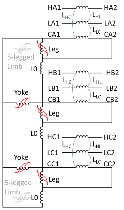
The principle of the modeling is to derive a topologically correct model with the core connected to an artificial winding on the core surface. Individual magnetizing branches are established for the yokes and legs dependent on their relative length and area (normally a value within limited range). A key feature is that magnetization is assumed to follow the Frolich equation which is fitted to Test Report data. This improves extreme saturation behavior since linear extrapolation above the Test Report data is avoided. The leakage inductance is modeled with an inverse inductance matrix (A-matrix), following the BCTRAN approach as documented in the Theory Book p. 6.21. Shunt capacitances and frequency dependent winding resistance is also considered.
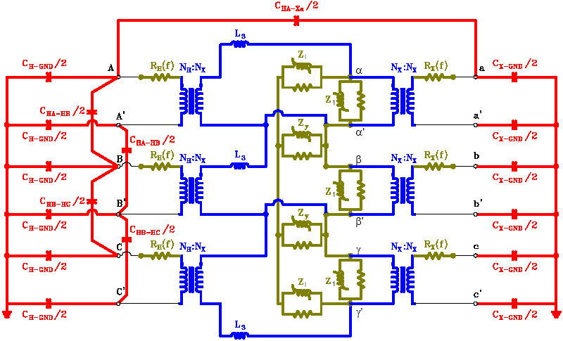
The transformer model consists of four parts (as shown in the figure below) :
•Inductance. Leakage reactance - > A-matrix
•Resistance. Winding resistance -> R(f)
•Capacitance. Shunt capacitance - C-matrix
•Core. Individual magnetization and losses for legs and yokes.

Fig. 1. Duality model for a 3-phase, two-winding transformer from MTU4.
The XFMR component support three sources of data:
•Design parameters. Winding and core geometry and material properties.
•Test report. Standard Test Report data like in BCTRAN. Capacitances and frequency dependent resistance added.
•Typical values. Typical text book values based on transformer ratings. Be careful with this as both design and material properties have changed a lot the last decades.
The inductive coupling of the windings is in reality not exactly as shown in Fig. 1, but follow the BCTRAN approach (with an additional fictitious core winding) as shown in Fig. 2.

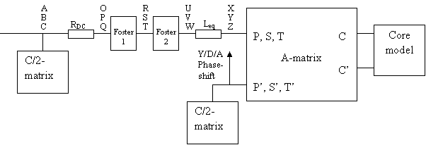
The overall node structure of the XFMR component in the final ATP file is shown in fig. 3.

Fig. 3. Node structure in the ATP-file.