The A-matrix is written to the ATP file with the AR notation with the resistances set to zero. The matrix has dimension [(nw+1)*np, (nw+1)*np] where nw is the number of physical windings, and the core is connected to the nw'th +1 winding, and np is the number of phases. In the MTU6 report each admittance in the A-matrix is written between the nodes PSTC and an extra set of nodes P'S'T'C' which finally are connected by switches to give the correct coupling and phase shift. In ATPDraw the extra nodes P'S'T'C' are omitted and the coupling and phase shift is produced directly when writing the A-matrix. In this way all possible phase shifts are supported. The extensions of the PST nodes are changed from ABC/DEF to XYZ in the presence of winding resistance (the user can turn the resistance off). The A-matrix has the following structure for a three phase transformer
 where
where  for a 3-winding transformer
The A-matrix is assumed to have no mutual coupling between the phases. The entire zero-sequence system is modelled in the core part. The Aw-matrix is established according to the BCTRAN approach from the EMTP RuleBook and section 5.2.4 p. 31 in MTU7. A routine for inverting the reduced A-matrix (MTU7 eq. (18)) is written based on the Gauss-Jordan routine with pivoting found in Numerical Recipes ver. 2.
Typical values
The leakage reactance is established from table 1, p. 28 in MTU7 (from J.J. Graininger & W.D. Stevenson: Power System Analysis, McGraw-Hill 1994) using the lowest value in the typical range. If the type of cooling is unknown forced-air cooling is assumed. A function interpX is written that interpolates linearly the table values (sent as a matrix in the function call) based on the voltage sent as parameter. All voltages larger than 700 kV (upper limit of table 1) are truncated down to 700 kV. In the case of a three-winding transformer the leakage reactance between the inner and outer winding is approximated as the sum of the other two.
XPS [pu] = interpX(table1, max(UP,US), Cooling)/100;
XST [pu] = interpX(table1, max(US,UT), Cooling)/100;
XPT [pu] = XPS+XST;
If is assumed that the secondary winding is the middle winding.
Test report
The leakage reactance is calculated from the standard test report data (positive sequence).
![]()
In the case of an autotransformer coupling the reactances are scaled
XST =1/(UP-US)*(XST*UP*US/(UP-US)+XPS*UP-XPT*US);
XPS =XPS*sqr(UP/(UP-US));
Design data
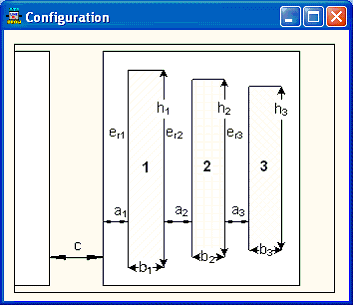
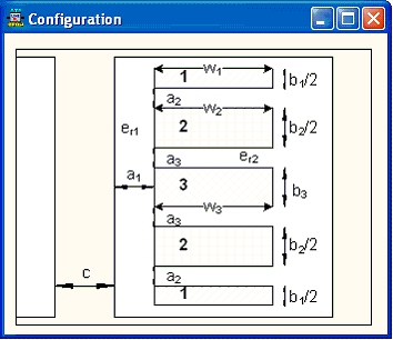
The leakage reactances are calculated according to MTU7 eq. (5)-(7) for a cylindrical winding configuration and according to eq. (9)-(11) for pancake windings. Pancake windings can be arranged in various ways, but the simple layout illustrated in MTU7 fig. 9 and 10 is assumed. The reactances are scaled to per unit based on the voltage across the PST windings, and the reactances are sorted according to the winding number that relates the PST sequence to the winding position on the leg.


Fig. 1. Configuration of the winding (left: cylindrical, right: pancake)
Cylindrical:
![]()
![]()
![]()
The indexes H, M and L refer to the outer, middle, and inner winding respectively. h is the average height of the two windings involved, Lmt is the equivalent circumference of the winding or leakage channel (2p\\r), a and b is the width of the leakage channel and winding respectively.
Pancake:
![]() ,
, ![]()
![]()
W is the average width of the two windings involved. a height of the leakage channel and b is the total height of the winding.
Handling of the core winding
The core winding is related to the leakage channel between the inner physical winding and the core. A parameter K=a1/a2 is used in MTU6/7 with a1 is the width of the inner leakage channel and a2 is the width of the leakage channel between the inner and the outer/middle winding. Various values are used in the MTU reports, but a fixed value K=0.5 is used in ATPDraw. If the pu leakage reactances XML, XMH, and XHL (L=inner, M=middle, H=outer) for a three winding transformer are given then the leakage reactances to the core winding are assumed to be
![]() ,
, ![]() , and
, and ![]()
The leakage reactances so far sorted according to the PST sequence are now sorted according to the inner-middle-outer sequence and leakage reactances related to the new artificial core winding are established according to eq. (14)-(16) in MTU7. After the Aw-matrix is established the reactances are sorted back to the PSTC sequence. The voltage of the core winding is equal to the voltage of the inner winding. This is the reason why the winding number is required for all type reactance data.
Scaling the Aw-matrix
The Aw-matrix is built on the reactance values in per unit sorted according to the PSTC sequence. The formulation in MTU7 chapter 5.2.4 is used. Finally the Aw-matrix is scaled by the various winding voltages and the single phase base power. For a Y of Auto-coupled winding the line-to-line voltage is divided by![]() .
.