The SATTRAFO component supports all possible phase shifts i Delta and Wye couplings as well as Auto-transformers and zig-zag couplings with phase shifts in the range <-60, 0> and <0, 60> degrees for two or three windings. A single-phase variant SATTRAFO1 with up to 6 windings replaced the two-winding TRAFO_S komponent in versjon 7.4. For the SATTRAFO components it is up to the user to obtain the per winding impedance (not strait forward from binary tests for more than 3 windings). The magnetization branch is always connected to the primary (1) winding.
The component dialog box of this transformer is shown in Fig. 1. With the button 3-leg core unchecked the model is a saturable transformer with low homo polar reluctance. Checking the 3-leg core button, turns the transformer into a TRANSFORMER THREE PHASE type with high homopolar reluctance, specified in the appearing R0-field. Checking the RMS button, enables specification of the saturation characteristic in RMS values for current and voltage on the Characteristic page. A conversion to flux-current values is performed internally in ATPDraw. If the button is not checked normal flux-current values should be entered. Four types of winding couplings are supported; Wye (Y), Delta (D), Auto (A), Zigzag (Z). The possible phase shifts (in degrees) can be selected from the combo boxes or in the case of a zigzag coupling be specified in an edit field. The tertiary winding can be turned on or of by checking the 3-winding button.
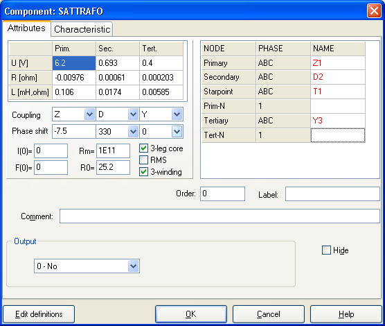
Fig. 1 General 3-phase saturable transformer dialog.
For an Auto-transformer the Primary winding must be of type A and the Primary winding is always connected in series with the Secondary. Some logic forces the Secondary to A with the Primary. If the Teritiary also is of type A it is connected in parellel with the Secondary with a common neutral point (this is a rather unusual configuration, however). The user must manually perform recalculation of the test-report data to obtain the voltage, resistance, and inductance values for Auto-transformers (ref BCTRAN).
For a zigzag transformer the Z winding is split in two parts (z and y) and the voltage, resistance and inductance for each part is automatically calculated by ATPDraw. Let U, R and L be the specified voltage, resistance and inductance in fig. 1 respectively. Let a be the specified phase-shift angle. Then
the turn ratio becomes n=sin(a)/sin(60-a).
The voltages are:
Uz=U/(cos(a)+n*cos(60-a))
Uy=Uz*n (as the winding voltage is proportional to the number of turns)
The resistances are:
Rz=R/(1+n)
Ry=R*n (as the winding resistance is proportional to the number of turns)
and the inductances are:
Lz=L/(1+n*n)
Ly=Lz*n*n (as the leakage inductance is proportional to the square of the number of turns)
No calculation is performed for the magnetizing branch or for the zero-sequence reluctance.
The SATTRAFO data in fig. 1 will result in the following ATP file, where the Z winding is split in two windings 1-2. An internal node T0002 is introduced between the two winding parts. The 3-phase node T1 is where the magnetizing branch is connected.
TRANSFORMER THREE PHASE TX0001 25.2
TRANSFORMER T1A 1.E11 0
1. 1.28
9999
1Z1A T0003C -.0084.103215.6797
2 T0003A -.0014.00279.93446
3D2A D2C .00061 .0174 .693
4Y3A .0002.00585 .4
TRANSFORMER T1A T1B
1Z1B T0003A
2 T0003B
3D2B D2A
4Y3B
TRANSFORMER T1A T1C
1Z1C T0003B
2 T0003C
3D2C D2B
4Y3C
The single-phase saturable transformer TRAFO_S can have 2 to 6 windings and the icon adapts accordingly. Fig. 2 shows an example with 4 windings.
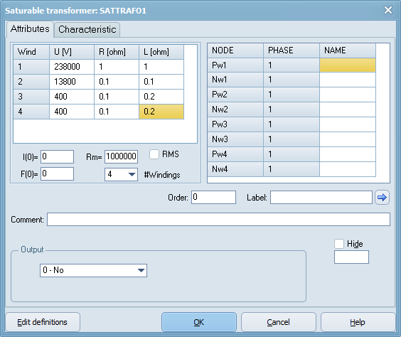
Fig. 2 Single phase saturable transformer component, 2-6 windings.