The BCTRAN transformer component is found in the selection menu under Transformers|BCTRAN. The component contains direct support of BCTRAN transformer matrix modeling. The user specifies input to a BCTRAN data case and ATP is the automatically execute to generate a punch file that is inserted into the final ATP file describing the circuit. The BCTRAN dialog is developed in close co-operation with Bruce Mork and Francisco Gonzalez Molina.
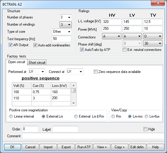
The BCTRAN dialog is shown in fig.1.

Fig. 1 BCTRAN dialog box.
Under Structure the user specifies the number of phases, the number of windings, the type of core (not supported yet, except for single phase cores, triplex), and the test frequency. The dialog box format adapts the number of windings and phases. The user can also request the inverse L matrix as output by checking AR output. An Auto-add nonlinearities button appears when an external magnetizing branch is requested as explained below.
Under Ratings the line-voltage, rated power, and type of coupling is specified. Under connection A (auto-transformer), Y and D is available and the phase shift menu adapts this settings with all types of phase shifts supported. If the connection is A or Y, the rated voltage is automatically divided sqrt(3) to get the winding voltage VRAT. If an Auto-transformer is specified the short-circuit impedances are recalculated as shown below, except when AutoTrafo by ATP is checked. When the Ext. neutral connections button is checked, all neutral points become 3-phase nodes that the user has to connect manually.
Under Factory test the user can choose either the open circuit test as shown in fig. 1 or the short circuit test as shown in fig. 2. Under the open circuit test the user can specify where the test is performed and where to connect the excitation branch. Normally the lowest voltage is preferred, but stability problems for delta-connected nonlinear inductances could require the lowest Y-connected winding to be used. The user can choose between the HV and LV, and TV winding for a three-winding transformer. The user can specify up to 6 point on the magnetizing curve. An empty cell marks the end of the characteristic. The excitation voltage and current is specified in % and the losses in kW. With reference to the RuleBook, the values at 100 % voltage is used directly as IEXPOS=Curr [%] and LEXPOS=Loss [kW]. One exception is when External Lm is chosen under Positive core magnetization. In this case only the resistive current is specified resulting in IEXPOS=Loss/(10*SPOS). SPOS is equal to the Power [MVA] specified under Ratings for the winding where the test is performed. If zero-sequence data is available the user can similarly specify it to the right. The values for other voltages than 100 % can be used to define a nonlinear magnetizing inductance/ resistance. This is set under Positive core magnetization. Specifying Linear internal will result in a linear core representation based on the 100 % voltage values. Specifying External Lm will result in calculation of a nonlinear inductance first as a Irms-Urms characteristic then automatically transformed to a current-fluxlinked characteristic (by an internal SATURA-like routine). The current in the magnetizing inductance is calculated as
Irms= sqrt((10*Curr*SPOS/3)^2-(Loss/3)^2)/Vref
where Vref is actual rated voltage specified under Ratings, divided by sqrt(3) for Y- and Auto-connected transformers.
The user can choose to Auto-add nonlinearities under Structure and in this case the magnetizing inductance is automatically added to the final ATP-file as a type 98 inductance. ATPDraw connects the inductances in Y or D dependent on the selected connection for actual winding for a 3-phase transformer. In this case the user has no control of the initial state of the inductor(s). If more control is needed (for instance to calculate the fluxlinked or set initial conditions) Auto-add nonlinearities should not be checked. But then the user must create separate nonlinear inductances. There is however a Copy feature that allows the user to copy the calculated nonlinear characteristic to an external nonlinearity. What to copy is selected under View/Copy (the + sign is added to indicate that only the positive sequence data are handled). To copy the fluxlinked-current characteristic used in type 93 and type 98 inductances Lm-flux should be selected.
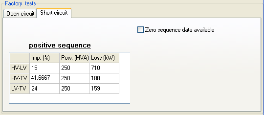
The short circuit data are specified as shown in fig. 2.

Fig. 2 Short circuiy factory test data.
With reference to the RuleBook; Imp [%] is equal to ZPOS, Pow. [MVA] is equal to SPOS, and Loss [kW] is equal to P. These three values are specified for all the windings. If an Auto-transformer is selected for the primary and secondary winding (HV-LV) (and if AutoTrafo by ATP is not checked), the impedances are recalculated based chapt. 6.7 in the Theory book (H.W. Dommel 1986) and an example shown by Laszlo Prikler in EEUG News in the Feb-May issue 2001:
Z*_HL =Z_HL*(VH/(VH-VL))^2
Z*_LT = Z_LT
Z*_HT =Z_HT*VH*VL/(VH-VL)^2 + Z_HL*VH/(VH-VL) - Z_LT*VL/(VH-VL)
where Z_LH, Z_LT, and Z_HT are the Imp. [%] values from fig. 2 and Z*_LH, Z*_LT, and Z*_HT are the values written to the BCTRAN file.
Zero-sequence data can also now be specified for 3-phase transformers.
When the user clicks on OK he is requested to store the data in a BCT-file preferably in the /BCT directory. This is a binary file stored in the project just like LCC-files for lines/cables. Then the user is offered to generate a BCTRAN-file and run ATP. This is really optional since often a new BCTRAN file will be required anyway during the final ATP-file generation. Trying to run ATP is a good practice however, since this will quickly warn the user about possible problems. The button Run ATP does the same thing and this is just a more manual way to request an ATP execution without leaving the dialog box. If the BCTRAN file is correct a punch file will be created. This file is directly included in the final ATP file and there is no conversion to a library file as for lines/cables. This means in practice that a new BCTRAN file will be created and ATP executed automatically (when creating the final ATP-file) each times the transformer's node names change.
There is also an Import button available so that the user can import BCT-files. The user can also store the BCT-file with a different name (Save As), which is useful when copying BCTRAN-objects. The View and Copy buttons is for the nonlinear characteristic. Copy transfers the selected characteristic to the Windows clipboard in text format with 16 characters fixed columns (the first column is the current). View displays the nonlinear characteristic in the View Nonlin window.
The BCTRAN component is found under Transformers|BCTRAN in the component selection menu.
The nodes appear automatically dependent on the selected connection and number of windings. The data specified in fig. 1 will result in the following icon

with 3 three-phase terminals and one single phase neutral point common to the primary and secondary winding. The label shows the transformer connection.
The BCTRAN component can be edited and connected to the main circuit as any other component.