The component LINE3 is handled in a special way in ATPDraw. The drawing and graphical appearance of the component is similar to Connections. The LINE3 component has no fixed size but stretches from node LEFT to node RIGHT in any direction. In the toolbar there is a special button to switch between drawing of Connections or LINE3. The Rubber band option applies also to LINE3.
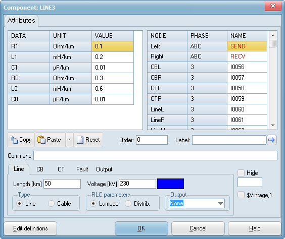
The component is found under Power System Toolbox in the Selection Menu and it is always 3-phase and the input is given as positive and zero sequence parameters. The line model can be lumped (PI-equivalent) or distributed (Bergeron).
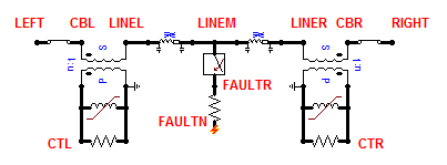
The line goes from node LEFT to RIGHT but has also several internal nodes for embedding of circuit breakers (CB), current transformers (CT) on both sides and a fault of user defines type and position. The figure below shows the meaning of all nodes.

On the Line tab there are options for graphical appearance. Cable or Line can be chosen. Cable gives a dashed thick line, while Line gives 3 parallel single lines. The voltage can also be specified and the a color will then be assigned as given under View|View options/PS Colors.

On the CB tab the user can specify opening/closing times of circuit breakers at each side. If the CB is turned on it will have a graphical appearance at the line end:
Empty: CB is closed at t<0
Crossed:CB is open at t<0
Lime: CB will change once during the simulation (solid: closed will open, crossed: open will close)
Black: CB will change twice during the simulation (is open at t<0 but will close and reopen).
On the CT tab the user can specify turns ratio, burden and a two-slope magnetization characteristic for CTs on both sides. The magnetization characteristic is given by the normal and saturated inductance values and the fluxlinkage at transistion. The help file gives the following suggestions for values:
n Turns ration Vs:Vp or Ip:Is (3000:5 -> n=600).
Rb Actual CT burden. Rated burden Rbr=VA/Isr^2. VA is CT rating, Isr is 5A (or 1A).
Lm Unsaturated magnetization inductance; Lm > Rbr/omega/e; e is accuracy in pu (~5%)
Fm Saturation point of CT; Fm > IX*VA/Isr*sqrt(2)/omega; IX is current factor (~30)
Linf Magnetization inductance in saturation; Linf << Lm
Turn saturation off by selecting Lm=Linf= high number (9999)
On the Fault tab the user can specify the fault location (0 to 100%) and type (all short curcuits pluss broken conductors) as well as fault resistance and onset+clearing times.
On the Output tab the user can specify output of steady-state power flow or currents on both sides (into the line) in a variety of formats.