Node overlap
Nodes will be connected if they directly overlap. There is a Gridsnap feature that always snap the nodes to the nearest 10 pixels, so if the nodes look connected, they are.

The user needs to be a bit careful when placing some components as there is a possibility of what-you-see-is-what-you-get violations as shown below. The user can inspect the given node names in the circuit to see if nodes indeed are given the same name. In the incorrect cases below, the user can force connection by given node names to otherwise disconnected nodes, but will then receive warnings about "same name of disconnected nodes" which could be annoying in the end.
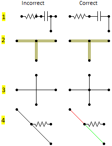
•Components are not connected if nodes are connected inside the icon, nodes must overlap. Shown in row 1 above. This example is rather clear, but users are allowed to create private icons that can increase the likelihood of missing overlap.
•In contrast to the Connection, it is not legal to connect nodes along the LINE3 component (like shown in the row 2 above). To the left, there is one horizontal line with a vertical line connected to it at the middle (incorrect), while to the right the horizontal line consists of two parts (correct). It is not possible to differentiate between the left (incorrect) and right (correct) drawing for LINE3, so be a careful.
•Connections will not be connected if they cross like shown at the row 3 above. In the correct case above, the vertical connection is split in two while the horizontal is continues.
•Diagonal Connections will not pick up "connected" nodes as shown in row 4 above. The correct figure to the right is illustrated with two connections of different color to clarify.
Connections between nodes
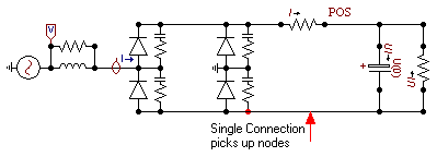
A horizontal or vertical connection will pick up any nodes connected to it. Diagonal connections will only connect to its endpoints.
Multi-phase vs. single-phase
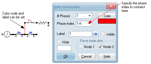
Single phase nodes can be connected to multi-phase. When drawing a Connection between nodes of different phases, the Edit Connection dialog pops up. The phase index must be specified in the dialog. The color is set automatically accordingly (phase A=red, phase B= lime, phase C=blue) but can optionally be changed, and a label can be added and made visible. In general, it is more correct to use phase 1, since phase A only holds when the node is not transposed. Normal 3-phase and single-phase Connections will default have Phase index equal to 0-@ and ATPDRaw will determine the appropriate phase index.
Current (or switch status) into control systems
Current must be taken from an electrical switch node. It does not matter which side of the switch you use to get the current, but the current direction is always measured from node FROM/SWF to TO/SWT. In case several switches are connected to the same node, the current though (or status of) the FIRST switch connected to the node is used. To prevent confusion, the user should only try to extract the current where there is one branch of switches connected. The current probe has an option "Add current node" and by checking this, two measuring switches are added in series and the middle point (no other switches should connect to this node) made available.
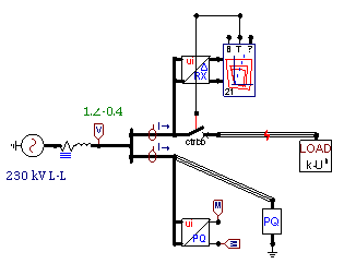
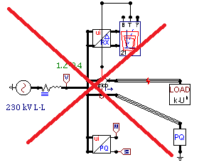
Connection of PQ and RX calculators, correct (left) and incorrect way (right). The right figure is incorrect because both switches are connected to the same node.
Circuit interaction with control systems (TACS and/or MODELS)
Project is solved in following sequence for each timestep: Circuit - TACS - MODELS
There is one timestep delay between solution of the circuit and the control system.
TYPE94 is a special, integrated component solved as a nonlinear device. It avoids the time delay in some cases by using the compensation method.
Circuit to TACS
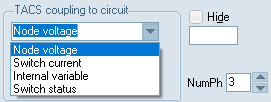
The Circuit variable object ![]() (EMTP_OUT) provides an interface for TACS HYBRID simulations. This object must be connected with an electrical node to pass node voltages, or the branch currents / switch status to TACS. The type of the variable sent to TACS is controlled by the Type settings in the EMTP_OUT component dialog box.
(EMTP_OUT) provides an interface for TACS HYBRID simulations. This object must be connected with an electrical node to pass node voltages, or the branch currents / switch status to TACS. The type of the variable sent to TACS is controlled by the Type settings in the EMTP_OUT component dialog box.
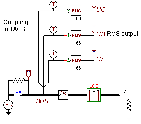
Coupling a 3-phase electrical node to TACS.
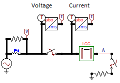
The circuit node where you connect the Circuit variable object ![]() (EMTP_OUT) to, must be unique inside TACS. You cannot specify both current and voltage for the same node, as these will get the same name in the control system an ATP will report an error. The figure below shows how both voltage and current should be extracted at each side of the switch.
(EMTP_OUT) to, must be unique inside TACS. You cannot specify both current and voltage for the same node, as these will get the same name in the control system an ATP will report an error. The figure below shows how both voltage and current should be extracted at each side of the switch.
Circuit to MODELS
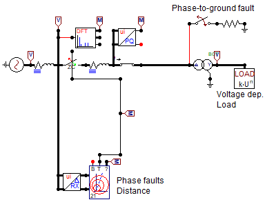
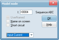
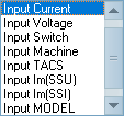
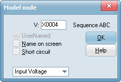
Electrical signals are connected directly to MODELS. There are no restriction related to duplication of control nodes. Inputs can be connected together like shown below where one node is set to current and the other to voltage. To define the type of input the user must click on the MODEL's node and select the input.
Electrical machines variables into TACS/MODELS
Getting machine variables into control systems is different for the two main types of machines in ATP as shown below.
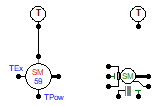
For synchronous machines type 58/59, the number of TACS nodes must first be specified inside the machine's dialog (1 in this case). Then the user must click on the machine control node and specify the type of variable. Finally the EMTP_OUT component is connected and "internal variable" and Synchronous machine is checked.
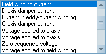
Setting of the control node of the machine

Setting of the EMTP_OUT object
For universal machines, the EMTP_OUT component is just added and the type of internal machine variable specified inside it. The machine number as given inside the machine's dialog must be used. This number can change during the circuit design, and this is not automatically updated inside the EMTP_OUT object.

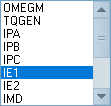
Since the mechanical network of universal machines is external, the mechanical speed and torque can be brought into the control system as electrical quantities (speed=voltage, torque=current). This is shown below where the mechanical torque is taken as a voltage into two different MODELS for speed and voltage control. Automatic initialization requires connection of on type 14 current source as shown on the mechanical side and one type 14 voltage source on the field side. This latter source must be declared before the incremental TACS source (type 60) and connected to the same node as this one (voltage sources connected to the same node are always added). This restriction does does not apply to the current sources on the mechanical side.
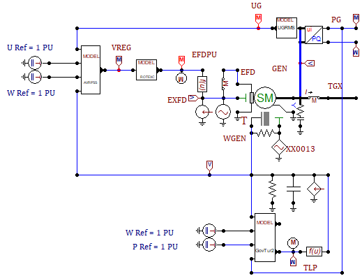
The machine controls in the figure above consists of MODELS in chain, and thus it is important that a model producing input to the next comes first in the ATP file. Use the Sidebar and its Project page (click Update first) to drag models in required sequence (top comes first). Also the controls above are basically meant for synchronous machines type 58/58 operating around 1 pu. TACS components are used to subtract 1 and scale the torque and field voltage to physical units for the incremental sources. This thus requires the TACS|Source/Model variable component connected to the TACS block input. ATPDraw v7.6 comes with multimass, governor and exciter models that simplifies the connections. The figure below shows an extract from example Exa_30 where the requirements now are that the UI2PQ3 and PSSW1 blocks comes before the Governor and Exciter blocks respectively. The reference values Vref, Wref and Pref should come from TACS DC sources with Tstart<0.

TACS/MODELS to Circuit
ATPDraw supports 7 components that can be controlled by TACS/MODELS (no difference between the type of control system). There are three found under Branches Nonlinear (TACSRES, TACSIND, TACSCAP), three under Switches (Tacs switch SW_TACS (=igbt), Valve SW_VALVE (=thyristor) and TRIAC), and one under Sources (TACS Source, TACSSOUR) than be set as voltage or current source.
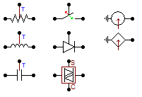
Controlled branch (resistor, inductor, capacitor)
Controlled switch
Controlled source (yes, connect to the electrical node, no control node for sources).
Note that the TACSSOUR component does not have a separate control node and the control signal is set directly on its output. The figure below shows the "peculiar" case of an apparently tail biting control, but where the input is a voltage (=speed) and the output controls a current source (=torque) and these can be connected together.
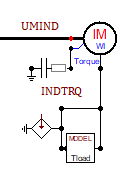
The control a floating current source must be manged via an ideal transformer or by controlling two sources with opposite polarity.
TACS to MODELS
TACS signals can be connected directly to a MODEL's input. Click on the MODEL's node and specify the input as TACS.
MODELS to MODELS
MODELs can be connected together and the input of one MODEL node set to Input MODEL (right click on the input node). There must be a correct sequence of the MODELs (Model providing output must come first).
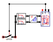
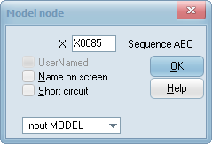
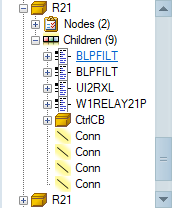
Connect MODELs together, specify Input MODEL in input nodes, make sure (drag &drop) the sequence is correct in the Sidebar/Project-Object tree according to the flow of information. Sorting option available under Edit|Arrange|Sort all Models to correct the sequence of Models.
MODELS to TACS
MODEL output can be sent back to TACS via the TMODVAR component found under TACS sources.