The COMTRADE objects where introduced in ATPDraw v7.1. They are based on open MODELS code that writes samples data to the LIS-file and reads back the data after the simulation. The user can select an arbitrary sampling frequency unrelated to the timestep of the simulation. The LIS-file technology puts some practical constraints on the number of samples and above one million should be avoided. The COMTRADE objects supports multiple runs, and has an option to create MatLab .mat files instead of the usual .cfg and .dat files.
There are three different comtrade objects:
COMTRADE: Has 3-phase inputs nodes (6 for analog channels and 3 for digital channels) and offers some direct interpretation of the inputs (channel names and voltage/current) in the required comtrade C7.111-1999 format.
COMTRADE1: Has a single multi-phase input and requires manual specification of the channels data. Typically, there is need for a packing object in MODELS that collects the channels from the circuit, perform possible pre-calculations, and synthesize all channels into a multi-phase node. The object supports 26 analog+digital channels.
COMTRADE2: Has two multi-phase inputs, one for analog and one for digital channels. Similar to the COMTRADE1 object a packing object is needed. The object supports up to 26 analog and 26 digital channels.
The example Exa_26.acp illustrates how to use the COMTRADE objects to generate comtrade files. The case is a single-pole reclosing after a ground fault phase A. Only the COMTRADE1 object is shown in Fig. 1 because the other options are similar. The timestep of the simulation is 125 µs and the power frequency is 60 Hz. The sampling frequency chosen in the COMTRADE1 object is on the contrary 1920 Hz, meant to illustrate how this can be selected independent from the timestep. A special trick using the COMTRADE objects is that a packing object is needed to stack first the analog then the digital channels. The user must specify the MODELS code for each case as shown below. The COMTRADE1 object requires declaration of a single output and 13 phases is chosen in this case with first 10 analog, then 3 digital channels. Inside the packing object, zero sequence voltage and current are calculated. Click on the packing object’s input nodes to select the type of input (voltage, current, switch status, MODELS).
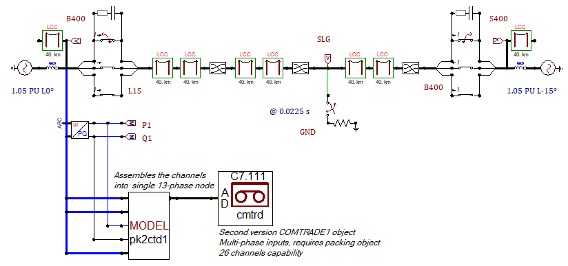
Fig. – Setting up creation of COMTRADE files with packing object.
In Fig. 1 there are three Models component in series, so the sequence of these objects must be correct. Control the sequence manually from the Sidebar|Project (click Update) or simply select Edit|Arrange|Sort all Models.
Packing object MODELS code.
MODEL PACK2CTD1 -- * * * User defined COMTRADE Signal 'Packer' * * *
INPUT V1ABC[1..3] -- 1st 3-ph Analog signals: L-N Voltages
I1ABC[1..3] -- 2nd 3-ph Analog signals: phase currents
P1, Q1 -- 1-ph Analog signal: P, Q powers
CBST [1..3] -- digital signals: line's CB pole status
OUTPUT CHA[1..13] -- Packed
VAR CHA[1..13] -- Signals
EXEC
CHA[1] := V1ABC[1]-- First pack signals into analog channels
CHA[2] := V1ABC[2]
CHA[3] := V1ABC[3]
CHA[4] := V1ABC[1] + V1ABC[2] + V1ABC[3] – Zero seq voltage 3*V0
CHA[5] := I1ABC[1]
CHA[6] := I1ABC[2]
CHA[7] := I1ABC[3]
CHA[8] := -(I1ABC[1] + I1ABC[2] + I1ABC[3]) -- 3I0 return
CHA[9] := P1
CHA[10] := Q1
CHA[11] := CBST[1]-- Then pack signals into digital channels
CHA[12] := CBST[2]
CHA[13] := CBST[3]
ENDEXEC
ENDMODEL
The COMTRADE object’s input dialog is shown in Fig. 6.86. The user can select an arbitrary sampling frequency and both up and down sampling is supported. The COMTRADE objects consist of open MODELS code that can be modified by the user, but the WRITE section must not be changed. The sum of the number of analog (NumA) and digital (NumD) channels must match the number of outputs of the packing object (13 in this case). Trigger is specified in the IEEE C37.111 standard and Tinit is additionally used to start the sampling.
On the Comtrade page (Fig. 3) the channel information should be provided according to the IEEE C37.111-1999 standard. The Comtrade file format can be ascii or binary, but in addition an option to store the data in a .mat MatLab v4 file is available. ATPDraw reads in the written data from the LIS-file and perform the necessary scaling to create appropriate .cfg and .dat files stored in the Result Directory with the name given as Filename. The time multiplier is added as an option since vendors tend to interpret the time scale a bit differently. The COMTRADE objects have a View option that plots the raw data read from the LIS-file. In a multiple run situation, only the last run is stored unless Merge results in multiple runs is checked.
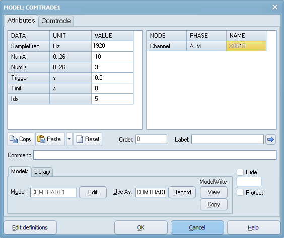
Fig. – COMTRADE object’s dialog. Standard MODELS page.
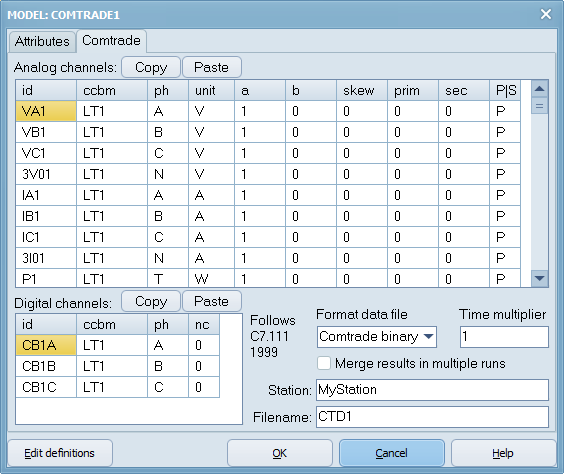
Fig. – COMTRADE object’s dialog, Comtrade page.
CTD1.cfg file:
MyStation,ATPDraw,1999
13,10A,3D
1,VA1,A,LT1,V,100.,0.0,0.0,-3664.9697,3664.9697,0.0,0.0,P
2,VB1,B,LT1,V,100.,0.0,0.0,-3509.9676,3509.9676,0.0,0.0,P
3,VC1,C,LT1,V,100.,0.0,0.0,-3475.72287,3475.72287,0.0,0.0,P
4,3V01,N,LT1,V,10.,0.0,0.0,-10277.314,10277.314,0.0,0.0,P
5,IA1,A,LT1,A,1.,0.0,0.0,-5078.8188,5078.8188,0.0,0.0,P
6,IB1,B,LT1,A,0.1,0.0,0.0,-10775.6608,10775.6608,0.0,0.0,P
7,IC1,C,LT1,A,0.1,0.0,0.0,-14554.9193,14554.9193,0.0,0.0,P
8,3I01,N,LT1,A,1.,0.0,0.0,-4971.95969,4971.95969,0.0,0.0,P
9,P1,T,LT1,W,1.E5,0.0,0.0,-6409.297,6409.297,0.0,0.0,P
10,Q1,T,LT1,VAr,1.E5,0.0,0.0,-6332.661,6332.661,0.0,0.0,P
1,CB1A,A,LT1,0
2,CB1B,B,LT1,0
3,CB1C,C,LT1,0
60.
1
1920.,1152
17/12/2020, 20:57:15.417000
17/12/2020, 20:57:15.427000
BINARY
1.
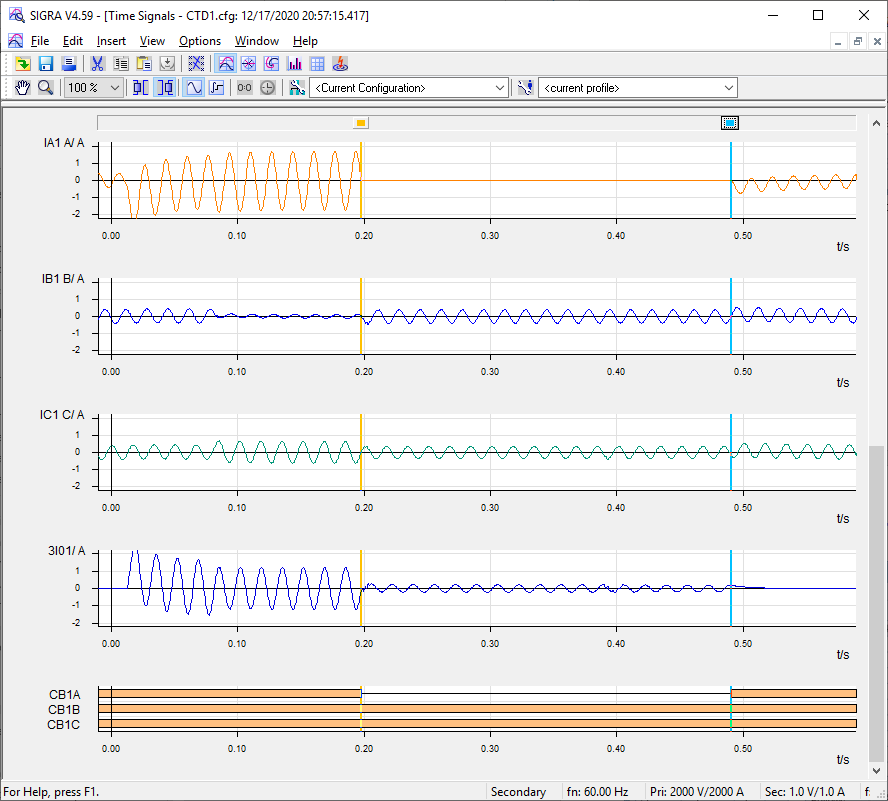
Fig. – Loading of the CTD1.cfg (and corresponding CDT1.dat) in SIGRA.