|
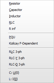
This sub-menu contains linear branch components. The name and the icon of linear branch objects, as well as a brief description of the components are given next in tabulated form. Data parameters and node names to all components can be specified in the Component dialog box, which appears if you click on the icon of the component with the right mouse button in the circuit window.
|
Selection |
Object name |
Icon |
ATP card |
Description |
Resistor |
RESISTOR |
|
BRANCH type 0 |
Pure resistance in W. Multi-phase |
Capacitor |
CAP_RS |
|
BRANCH type 0 |
Capacitor with damping resistor. C in mF if Copt=0. Multi-phase |
Inductor |
IND_RP |
|
BRANCH type 0 |
Inductor with damping resistor. Inductance in mH if Xopt=0. Multi-phase |
RLC |
RLC |
|
BRANCH type 0 |
R, L and C in series. Dynamic icon. Multi-phase |
R inf |
RINF |
|
BRANCH type 0 |
General resistor to ground to fix floating-subnetwork problems Multi-phase |
PQU |
PQU |
|
BRANCH type 0 |
Resistance and Inductance or Capacitance calculated internally based on PQ and U=voltage. Multi-phase |
Kizilcay F-dep |
KFD |
|
BRANCH IV.I |
High order admittance transfer in frequency (s) or time (z) domain |
RLC 3-ph |
RLC3 |
|
BRANCH type 0 |
3-phase R, L and C in series. Independent values in phases. Dynamic icon. |
RLC-Y 3-ph |
RLCY3 |
|
BRANCH type 0 |
3-phase R, L and C, Y coupling. Independent values in phases. Dynamic icon. |
RLC-D 3-ph |
RLCD3 |
|
BRANCH type 0 |
3-phase R, L and C, D coupling. Independent values in phases. Dynamic icon. |
C : U(0) |
CAP_U0 |
|
BRANCH + initial condition |
Capacitor with initial condition. |
L : I(0) |
IND_I0 |
|
BRANCH + initial condition |
Inductor with initial condition. |
